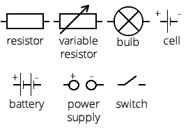
You need to know the following circuit symbols for this module:
Resistance and current:
Current in a wire is a flow of electrons which carry charge
Resistance (Ω) = voltage (V) ÷ current (A)
A longer wire produces higher resistance, this is how variable resistors (rheostats) work - by changing the length
Metals are good conductors because they contain positively charged metal ions surrounded by a 'sea' of delocalised electrons which are negatively charged
Resistance happens when electrons collide with the positive metal atoms. This increases the atom's energy by causing it to vibrate more and therefore temperature increases
Resistance increases as a wire gets hotter
Ohmic and non-ohmic devices:
A resistor obeys Ohms law (resistance = voltage ÷ current) - as current increases, voltage increases linearly
A filament lamp doesn't obey Ohms law because resistance increases as current increases, with a curve on a voltage-current graph
Potential divider circuits:
Potential dividers are used to produce a required voltage
2 or more resistors in series increase the resistance of the circuit. Calculate the total resistance by adding the resistance of each resistor
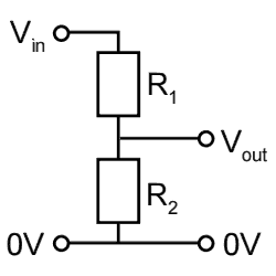
Here is a potential divider circuit:
When there are two resistors in a potential divider circuit, the output resistance is calculated as follows (using the names of components from the diagram above): Vout = (R1 ÷ (R1 + R2)) x Vin
When the resistance of R2 is much greater than R1, Vout is approximately the same as Vin
When the resistance of R2 is much less than R1, Vout is approximately zero
When the resistance of both R1 and R2 is about the same, Vout will be about half of Vin
The three points above can be proven with the equation listed above
Resistors in parallel:
If resistors are placed in parallel, total resistance is found using: 1 ÷ total resistance = (1 ÷ R1) + (1 ÷ R2) + (1 ÷ R3) (etc for the number of resistors present)
Placing resistors in parallel rather than in series reduces the total resistance of the circuit
LDRs and thermistors:
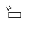
Light dependant resistors (LDRs) respond to changes in light levels - as light increases, resistance decreases. This is the symbol:
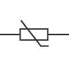
Thermistors are temperature-dependant resistors. As temperature increases, their resistance decreases. This is the symbol:
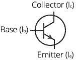
Transistors:
The transistor is the basic building block of electronic components - the average computer will have at least several hundred million of them
They are electronic switches; a small base current (Ib) can switch on a greater current outputted by Ie, from Ic. This is shown in the diagram of an NPN transistor:
Transistors can be combined to make logic gates. The input signals for these is usually either a high voltage (5V) or low (nearly 0V)
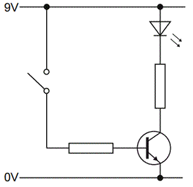
A transistor can be used as a switch for an LED: The triangle symbol at the top is the light emitting diode (LED)
Logic gates:
OR gates: if input X OR input Y is high, the output is high. The same happens if both X and Y are high
AND gates: if input X AND input Y is high, the output will be high
NOT gates: if the input is high, output is low, and vice-versa
NOR gates: an OR gate combined with a NOT gate to reverse the output
NAND gates: an AND gate combined with a NOT gate to reverse the output
Truth tables show how logic gates behave with their inputs and outputs. Here is a truth table for an OR gate:
Input X
Input Y
Output
0
0
0
0
1
1
1
0
1
1
1
1
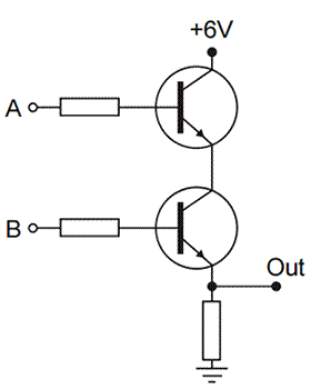
An AND gate can be created using two transistors, like this:
Other logic gates can also be made using a combination of two transistors
More on logic gates:
The output current from a logic gate is able to light an LED
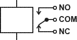
A relay can be used as a switch. This is the symbol for a relay: Because current output from logic gates is low, a relay can be used to switch on a larger current if the logic gate output is a 1 (on). This is useful in appliances like washing machines and heaters
Potential divider circuits can be used to connect thermistors or LDRs to logic gates. The LDR/thermistor is used as the top resistor, so that when it's dark/cold, resistance is high and the input to the logic gate is low, and the reverse for when it's light/hot
Magnetic fields:
A current carrying wire has a circular magnetic field around it, made of concentric circles (many circles around the same centre) in a straight wire
If the direction of current is reversed, the magnetic field is reversed
In a solenoid (a long piece of wire in several coils), the magnetic field is the same as that of a bar magnet - from N to S in semicircles
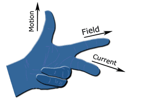
Fleming's left hand rule:
This is used to predict the direction of the force on a current-carrying wire
The direction of the current, magnetic field and motion are all at right angles to each other
This only works with the left hand
The first finger - field - points to the direction of the magnetic field from north to south
Motors:
Motors are found in washing machines, CD players, food processors, electric drills, fans, windscreen wipers and many more
They transfer energy to the load (useful) and to the surroundings (as waste), in heat
The motor spins faster when the number of turns on the coil is increased, the size of the current is increased or the strength of the magnetic field is increased
The direction of the current in the coil is reversed every half turn in a DC motor, so a split-ring commutator is used to ensure that the force (the spinning axle) is always in the same direction
A radial field increases the force on the coil and keeps the force constant
The dynamo effect:
Electricity can be generated by moving a wire near a magnet or moving a magnet near a wire - these induce a voltage in the wire
A voltage is induced across a coil when the magnetic field within it changes
Generators:
A generator is a motor working in reverse
The rotation of a magnet inside a coil induces an alternating current because the current direction changes every half turn
Generators contain slip rings and brushes which allow the coil to spin without winding the wire around itself
Electricity:
Electricity is useful because it allows energy to be stored and transmitted easily
In the UK, mains electricity is at 50 Hz
Electricity is generated in a power station when an electromagnet rotates inside coils of wire - Increasing the rotation speed increases current and frequency of the voltage generated - Increasing the number of turns on the electromagnet increases the magnetic field, inducing a greater voltage
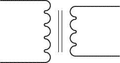
Transformers:
Transformers are devices which increase or decrease the voltage of AC
Power is not lost or gained because decreasing the voltage would increase the current and vice-versa
The symbol:
Transformers have two coils wrapped around an iron core; the primary (which the input current is connected to) and the secondary coil which is the output current in the desired voltage
Isolating transformers used in bathroom shaver sockets are used for safety as water and steam could lead to electrocution or circuit damage. They consist of equal numbers of turns on the primary and secondary coils
Step-up transformers have more turns on the secondary coil
Step-down transformers have more turns on the primary coil
In the equations in this section, Vp is the voltage across the primary coil, Vs is the voltage across the secondary. Np is the number of turns on the primary coil and Ns is the number of turns on the secondary
Vp ÷ Vs = Np ÷ Ns
Reducing transmission loss:
Power is transmitted with a high voltage and low current because high currents produce more heat, which is waste. This is shown by the equation: power loss = current2 x resistance
Not all transformers are 100% efficient though
Power = current x voltage can be used to calculate output power from the input power - VpIp = VsIs where I is current and V is voltage
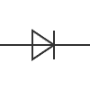
Diodes:
A diode is a device which allows current to flow in one direction only
Current flows in the direction indicated by the arrow shape in the symbol
If current can pass it's called a forward-biased direction and if no current can pass it's reverse-biased
Resistors are used in series with diodes to protect it
Diodes usually require at least about 0.6V to work
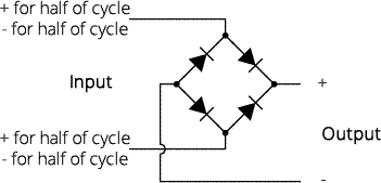
Rectification:
Rectifier circuits convert AC to DC power
A single diode prevents one half of an AC wave from passing through, for example everything below the x axis. So it's removed by the diode. This is half-wave rectification
Full wave rectification requires four diodes in a bridge circuit
However, the output will still have variation in voltage. So capacitors are used to smooth this
Capacitors:
Capacitors store small amounts of charge, and this is the circuit diagram symbol:
When a DC supply is connected, the capacitor becomes charged and the voltage across it increases until it is equal to the supply voltage
When it is connected to something that will consume the power, the voltage decreases as the capacitor discharges