Where = displacement (), = initial velocity (), = final velocity (), = time () and = acceleration ():
If an object is uniformly accelerating, average velocity =
10, 11 Displacement/velocity/acceleration - time graphs:
On a displacement-time graph, - the gradient at a point is the velocity at that time (the instantaneous velocity) - to get the average velocity, divide the overall displacement (i.e. the final displacement minus the initial displacement) by the time of the entire graph
On a velocity-time graph, - the gradient is equal to the acceleration - the area under the graph is the displacement
On an acceleration-time graph, - the area underneath is the change in velocity. If the area is 0 square units, the object is moving with constant average velocity
Remember that displacement, velocity and acceleration are vector quantities (see 12), so they can be positive or negative. So usually you would give a decelerating object a negative acceleration
How the above are derived:
To find the units of the gradient of a graph, divide the quantity by the quantity. For example, the gradient of a velocity-time graph is , acceleration
To find the units of the area underneath a graph, multiply the quantity by the quantity. For example, the area under a velocity-time graph is , displacement
Techniques:
To find the gradient of a curved graph, find the tangent at the point you are measuring at and use
If you're finding the area underneath a curved graph, split it into small chunks (boxes and triangles, or trapezia). Calculate the area of each chunk and then sum these areas to find the approximate distance travelled
12, 14 Scalar and vector quantities:
A vector has a magnitude and direction
A scalar quantity has a magnitude only
Vectors are drawn with arrows above them and are sometimes printed in bold italics
They can also be drawn as an arrow. The direction of the arrow indicates the direction of the vector, and the length is proportional to its magnitude
Add vectors to find the resultant (overall magnitude and direction): draw them tip-to-tail and use a ruler/trigonometry to calculate the resultant (distance from the tail of the first to the tip of the last)
Examples of scalar quantities:
Mass
Electric charge
Energy
Temperature
Time
Length
Speed
Work
Examples of vector quantities:
Force
Displacement
Momentum
Weight
Velocity
Acceleration
13 Resolving vectors:
Resolving a vector is the process of taking its overall magnitude and direction and using it to find its magnitude in two directions at right angles to each other. For example, if you are travelling at north-west, your velocity in the west direction would be about (°)
Use and to calculate the two component forces from the resultant - the hypotenuse
This can also be done by drawing a right-angled triangle with the hypotenuse as the overall vector (the one you are resolving) and measuring the sides with a ruler to find the components
The two components can now be separately used for calculations
14 Finding a resultant vector:
This is the opposite of resolving - here you'll have the two components and will need to find the resultant (hypotenuse)
Use Pythagoras' theorem to calculate the magnitude (magnitude = )
Use to calculate the direction (sketch the triangle first)
If you are asked to do this for two components which are not at right angles to each other, draw them tip-to-tail, fill in the third line to create a triangle, and use a protractor and ruler to find the resultant
15 Projectiles:
The vertical motion and horizontal motion of a projectile are independent of each other
Assuming air resistance is negligible, a projectile will continue at constant horizontal velocity
Vertically, a projectile will obey the equations of motion for uniform acceleration (see 9)
Find the time for the projectile to reach its highest point by using the vertical component of the initial velocity (acceleration )
To get the total travel time, multiply this by 2 (because the projectile will rise to its maximum height and then fall back down again at the same rate)
By multiplying the horizontal component of the initial velocity by the total travel time, the horizontal distance travelled can be calculated
16 Free-body force diagrams:
Free-body force diagrams show all of the forces acting on a body with arrows
The diagrams should not show the forces that the body exerts on other bodies
You can use free-body force diagrams to help calculate if an object is in equilibrium
A dot can be used to represent the body because it is the centre of gravity
If possible, you should make the lengths of the arrows proportional to the size of the force they represent. For example, if a body is accelerating in free fall, the arrow should be longer than the atmospheric drag arrow
Examples of forces on objects: - (friction) - (gravity) - (reaction force due to Newton's third law)
If you know the numeric value of forces, you should write those next to the arrow
17, 20 Newton's laws:
Newton's first law states that an object continues at a constant velocity/remains at rest, provided that there is no external force acting on it (a force is needed to change velocity)
Newton's second law states that acceleration is produced when force acts on a mass, and this acceleration is directly proportional to the magnitude of the force
Newton's third law states that forces always occur in equal, opposite pairs. The pairs are also always of the same type (e.g. both kinetic). In other words, if object A exerts a force on object B, object B will exert an equal and opposite force on object A
:
force () mass () acceleration ()
is the symbol for 'the sum of'. So is the sum of all forces. Because force is a vector quantity, represents the resultant (overall) force
This equation uses Newton's second law because it shows that and are directly proportional
If we substitute into the equation, we get , showing that there is no overall force if an object is not accelerating - i.e. Newton's first law
Terminal velocity:
Terminal velocity is reached when the weight of a falling object is equal to the upwards force (e.g. drag). Since there is no overall force, the acceleration will be 0 (Newton's first law)
18 Gravity:
Close to the surface of Earth,
This means that any object in free fall has an acceleration of about
weight () mass () gravity ()
gravitational field strength () force () mass ()
19 Determining the acceleration of a freely falling object (CP 1):
Light gates can be used to accurately measure the time for an object to fall a specific distance
Set up two light gates and measure the distance between them with a metre rule
Drop a long thin object through the top light gate and with a data logger, record the time it takes to pass through them
This should be repeated three times (or more if one result appears to be anomalous) and then with different distances
Because we know the displacement, starting velocity (), and time, an equation can be selected to calculate the acceleration;
This equation can be rearranged to form, from which we can find that on a graph of displacement against time squared, the acceleration due to gravity is the gradient multiplied by 2
This answer should be close to the actual value, about
21 Momentum:
momentum () mass () velocity ()
22 Conservation of linear momentum:
Momentum is always conserved, this is the law of conservation of linear momentum. So total momentum after a collision total momentum before the collision
Because , this can be expressed as where - is the mass () - is the initial velocity () - is the final velocity ()
Momentum and Newton's laws:
Newton's second law can be expressed in terms of momentum; the rate of change of momentum is directly proportional to the resultant force acting on the object
Due to Newton's third law, the momenta of both objects are equal. For example, when firing a gun, the bullet's momentum and the gun's momentum (due to recoil) are equal and opposite
23 Moments:
If you have a plank of wood lying on a pivot, the further away from the pivot you place a mass, the more it will rotate - This ability to rotate can be calculated and is called a moment - The total clockwise moment about a point is the sum of all moments which cause a clockwise rotation about that point - The total counter-clockwise moment is the opposite of this
moment about a point () = force () perpendicular distance (i.e. distance from the force to the point) ()
The perpendicular distance, , is the distance connecting the pivot point and line of action of the force
At equilibrium, the clockwise moment is equal to the counter-clockwise moment and all forces acting on the object must have a resultant force of zero
24 Equilibrium:
An object is in equilibrium if its forces are balanced
Due to Newton's first law, an object in equilibrium will not be accelerating
The vectors of the forces acting on a body can be drawn tip-to-tail. If they connect to create a closed shape, the body is in equilibrium
Centre of mass/gravity:
The centre of mass is a location on a body where if a force is applied, the effect is the same as if the force was applied equally to the whole body
It is not necessarily in the centre of an object - if it's heavier on one side, the centre of mass will be closer to that side
At equilibrium, the moments around the centre of mass will sum to zero. This can be used to find the centre of mass of a body
An object will fall over if, when drawn rotated at the angle you are testing for, a vertical line drawn straight down from the centre of mass doesn't pass through the edge that would usually be in contact with the surface it's on
25 Work:
Work is done when a force moves something, transferring energy
For example, if you lift something up, you do work against gravity, and kinetic energy is transferred to gravitational potential energy
Work is defined as: work () force () displacement (in the direction of the force) ()
To calculate the work done when the force is acting at an angle to the distance, calculate the component of the force in the direction of motion and multiply that by the displacement
26 Kinetic energy:
The kinetic energy of a moving object can be calculated with , where - is the kinetic energy () - is its mass () - is its speed ()
27, 28 Gravitational potential energy:
GPE is the energy something gains when lifted up (i.e. the work done to lift it). This is because energy is conserved, and this GPE will be converted into kinetic energy when the object falls
change in gravitational potential energy () mass () gravitational field strength () change in height ()
For example, if an object of mass is lifted by , it gains
29 Power:
Power is the energy transferred or work done per second
power () energy transferred () time ()
power () work done () time ()
30 Efficiency:
Although energy is never created or destroyed, it can be converted into non-useful energy (e.g. heat from a lightbulb)
efficiency useful energy output total energy input
efficiency useful power output total power input
Multiply these by 100 to get the percentage efficiency
31, 32, 34, 35 Current:
Current is measured in amperes () with an ammeter (connect in series)
it is the rate of flow of charged particles through a component in a circuit
There is never a 'build-up' of current in a circuit
Charge:
Charge is measured in coulombs ()
the charge in 1 second with of current
where - is the current () - is the time () - is the charge passing during that time ()
Potential difference:
pd is measured in volts ()
It is the work done per unit of charge moved
where - is the potential difference () - is the work done () - is the charge that the work is being done on ()
Conservation of charge:
Charge and current are conserved in a circuit
In a series circuit, the current through each component is the same, but the potential difference across high resistance components will be higher because more work needs to be done to move the charge carriers through them
At a junction in a parallel circuit, the sum of the current flowing in equals the sum of the current flowing out
33 Electrical resistance:
Charge flows more easily if there is less resistance in a circuit
Resistance is measured in ohms (), and , because
There will be a resistance of if makes a current of flow through it
Ohmic devices:
If the resistance of a material is constant over a range of pds (under constant physical conditions), it is considered ohmic; so the pd is directly proportional to current ()
Since there will be error when measuring current and pd in a conductor, a device can be considered ohmic within the limits of experimental uncertainty if against can be plotted on a graph with a straight line passing within all of the error bars/boxes
36 Combining resistors:
In a series circuit, , therefore and
In a parallel circuit, the same can be done to get
Deriving for a parallel circuit with emf :
so
so
The s cancel to give
37 Power:
power () energy transferred () time taken () (this is in the mechanics section of the formulae sheet but it works for electricity too)
power () potential difference () current ()
work done () potential difference () current () time ()
The equations in this section can be combined to form - - -
38 Current-potential difference graphs:
With an ohmic device, the current-potential difference graph will be a straight line with a positive gradient
Filament bulbs have a similar relationship (current increases with potential difference), however the graph would not be a straight line, with rate of change decreasing as potential difference increases:
With an NTC thermistor, resistance decreases as temperature increases, with resistance decreasing fastest at lower temperatures (it is an exponential function):
Diodes do not conduct until a certain potential is reached and only allow charge through in one direction:
39 Resistivity:
Electrical resistivity is a measure of how well a material resists, regardless of size
Resistance is directly proportional to the length of a conductor and inversely proportional to cross-sectional area
These properties can be combined to find resistivity: resistance () resistivity () length () cross-sectional area ()
A good conductor has low resistivity
Insulators have very few free electrons compared to conductors which have many
When a semiconductor is heated, electrons are freed making it a better conductor. Similarly, LDRs (light-dependent resistors) free electrons when lit
Comparing resistivities:
Resistivities can range by many orders of magnitude, so a logarithmic scale is therefore often used when displaying them on a graph
When the temperature of a resistor is increased, the lattice ions vibrate more. This reduces the kinetic energy of the delocalised electrons and therefore reduces the drift velocity
In different resistors, charge carrier density varies widely and therefore resistivities for different materials can be very different
40 Determining the resistivity of a material (CP 2):
Find the diameter of the wire with a micrometer in several places and find the mean. Convert to metres and find the cross-sectional area with
Attach the wire to a ruler and use crocodile clips to create connections
Attach a power supply, an ammeter (in series) and a voltmeter (in parallel)
Adjust the length and record the length, current and pd
Plot a graph of resistance against length and find the gradient. The line should be straight and pass through the origin
Multiply the gradient by the cross-sectional area in to get the resistivity
Resistivity is only for a specific temperature, and current in a resistive wire increases temperature, so aim to keep the current low or the wire at a constant temperature
41:
Charged particles have a drift velocity, their average velocity in the direction of flow (it is quite low as they won't travel in a straight line)
current () number of charge carriers per (count/) electron charge (from data sheet) () average drift velocity () cross-sectional area ()
An electron has the charge and this constant is represented by the symbol , or in this equation,
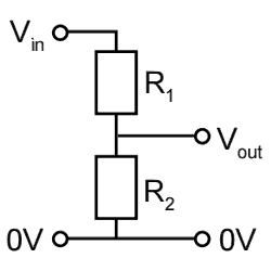
43, 44 Potential divider circuits:
A potential divider circuit produces an output potential difference which is a fraction of the input potential difference
A potential divider is shown below:
When there are two resistors in a potential divider circuit, the output resistance is calculated with
You need to memorise this equation. The numerator of the fraction must be the resistance of the resistor which you're taking the output potential difference from (so in the circuit diagram above)
So the output voltage will be greatest if you have a high resistance resistor between your and terminals for the output
An LDR has high resistance in the dark and low with lots of light. An NTC thermistor has high resistance at low temperatures. Therefore, an LDR/thermistor could be used in place of
45 Internal resistance and emf:
emf, electromotive force (), is a measure of energy (not force) transferred by a power supply for each coulomb of charge - The emf of the power supply is equal to the sum of potential difference across all other components in a series circuit - In a parallel circuit, the pd across each component is equal to the emf of the power source
All power sources have internal resistance due to the materials they are constructed from
It is indicated on a circuit diagram with a cell/battery marked with (or the numeric value for emf) in series with a resistor labelled with a lower-case (or the numerical value for internal resistance), and a dotted line box drawn around the two
The external load's resistance is marked with an upper-case
, therefore and
Terminal pd is the potential difference across the terminals. At zero current flowing, this is the same as the emf
So terminal pd is represented by the in the above equations
is sometimes referred to as lost volts
46 Finding the emf and internal resistance of a cell (CP 3):
The above equation () can be rearranged to get
By comparing this to the equation of a straight line graph (), the -intercept of a pd-current graph is the emf and the negative of the gradient is the internal resistance (the graph should have a negative gradient and not pass through the origin)
Use this graph to calculate the internal resistance and emf of a cell. Use a range of resistors or a variable resistor. Connect the voltmeter in parallel with the load resistor and ammeter in series, as shown in the below circuit diagram
47 Resistance and temperature:
Some conductors have a resistance which linearly increases with temperature, PTC (positive temperature coefficient)
Many are also NTC (inverse relationship)
Cells:
A cell is shown below. The longest vertical line is the positive terminal
An easy way to remember this is to draw a P and N like this:
Modelling current:
Conductors have charged particles (free electrons) which can move. An applied voltage causes electrons (negative) to move towards the positive terminal, creating a current
Because current is a measure of the rate of flow of these particles, it depends on their travel speed
Modelling resistance:
Materials are made from vibrating ions, and an increase in temperature (energy) makes them vibrate more vigorously
Electrons moving through the material are slowed due to collisions with the vibrating ions, and there are more collisions at higher temperatures. This is why most conductors are PTC
Additionally, more electrons are released with a rise in temperature. In some materials, semiconductors, this outweighs the resistance increase due to vibrating atoms, leading to a negative temperature coefficient, resistance decreasing at higher temperatures
NTC thermistors are usually made from a semiconductor. This is why resistance decreases as their temperature increases
Semiconductors are useful in electronics - they can be combined to form diodes and logic gates
48 LDRs:
Some semiconductors release electrons when they absorb photons, this property is used in light-dependent resistors (LDRs):
Resistance-light intensity graph for an LDR
So LDRs work in the same way as NTC thermistors, except that the energy comes from light instead of heat energy